
5G NR Synchronisation Signals (PSS and SSS): How a Phone Finds a Cell From Nothing
PSS and SSS explained from the UE's point of view: what each signal gives the receiver, how the PCI is built from them, and why NR has 1008 cell identities.
Start from the UE's problem
Imagine a UE that has just been switched on. It knows the band it is allowed to use and nothing else. It does not know:
- where in the band the cell is (frequency),
- when the OFDM symbols and frames start (timing),
- which cell it is (identity),
- whether the timing it eventually finds is the beginning or the middle of a frame.
The synchronisation signals exist to answer exactly these questions, in this order, using the minimum possible prior knowledge. Everything about their design makes more sense once you see it as "what can a receiver with zero knowledge detect?".
The mental model: a lighthouse with two lamps
A lighthouse tells a ship two things: "there is land here" (the flash itself) and "this is which lighthouse" (the flash pattern). NR does the same with two signals:
- PSS is the flash. It is one of only three possible patterns, so the UE can search for it cheaply. Finding it gives coarse timing and frequency alignment, plus one-third of the cell identity.
- SSS is the pattern that identifies the lighthouse. It is one of 336 patterns, and it can only be decoded after PSS has given timing. It supplies the remaining two-thirds of the cell identity.
Together they give the Physical Cell Identity (PCI).
Building the PCI
The PCI is split into two parts:
- N_ID^(2) ∈
{0, 1, 2}— carried by the PSS - N_ID^(1) ∈
{0, 1, …, 335}— carried by the SSS
and combined as:
PCI = 3 × N_ID^(1) + N_ID^(2) → 0 … 1007 (1008 PCIs)
LTE had 504 PCIs (168 × 3). NR doubled the SSS space to 336 to give planners more room in dense deployments. A useful sanity check: PCI mod 3 tells you which PSS the cell uses. Neighbouring cells sharing the same PSS make the first detection stage harder, which is why PCI mod 3 planning is still a thing in NR.
PSS: the cheap-to-find signal
What it is (TS 38.211 §7.4.2.2): a length-127 m-sequence (a maximal-length shift-register sequence), BPSK modulated, with three cyclic shifts giving the three N_ID^(2) values.
Why an m-sequence? Because m-sequences have an almost ideal autocorrelation: correlate the received signal against the known sequence and you get a sharp spike exactly when the timing is right and near-zero elsewhere. A UE searching blindly can slide a correlator across time and simply look for the spike. It only needs three correlators (one per N_ID^(2)), which is why PSS detection is affordable even before the UE knows anything.
What the UE gets from PSS:
- OFDM symbol timing (where symbols start)
- Coarse frequency offset correction (the UE's oscillator is not yet locked to the cell)
- N_ID^(2)
Where it sits: the first OFDM symbol (symbol 0) of the SS/PBCH block, occupying the central 127 subcarriers of the block's 240 subcarriers (subcarriers 56–182). The remaining subcarriers in that symbol are left empty as guard.
SSS: the identity signal
What it is (TS 38.211 §7.4.2.3): a length-127 Gold sequence — the product of two m-sequences. The two generator polynomials are cyclically shifted by amounts derived from both N_ID^(1) and N_ID^(2), so the SSS is tied to the PSS the UE already found.
Why a Gold sequence? A single m-sequence family gives you only a handful of good sequences. Gold sequences give a large family (here, enough for 336 × 3 combinations) with low cross-correlation between members, so the UE can distinguish 336 candidates reliably. The price is that they need a known timing reference to decode — which PSS has already provided.
What the UE gets from SSS:
- N_ID^(1) → together with N_ID^(2), the full PCI
- A better channel/frequency estimate (the SSS is a second known signal)
- Nothing about frame timing yet — that comes from PBCH
Where it sits: the third OFDM symbol (symbol 2) of the SS/PBCH block, the same 127 central subcarriers as PSS. Symbol 1 between them is PBCH.
Two signals, two jobs — the layout
SS/PBCH block (4 OFDM symbols × 240 subcarriers)
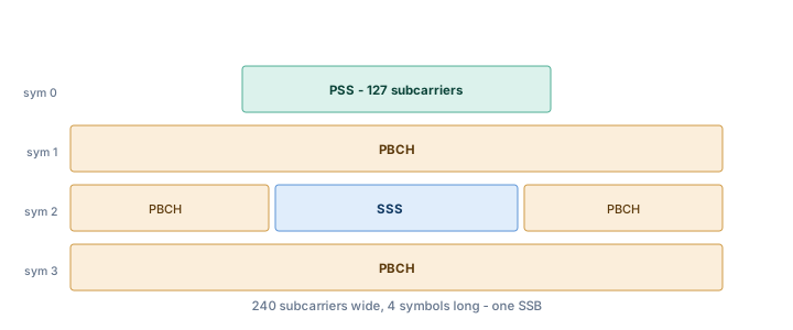
Symbol 0: [ guard ][ PSS 127 sc ][ guard ]
Symbol 1: [ PBCH 240 sc ]
Symbol 2: [PBCH 48][ SSS 127 sc ][PBCH 48]
Symbol 3: [ PBCH 240 sc ]
Notice that PSS and SSS are not adjacent. Putting PBCH in between (symbol 1) and around the SSS (symbol 2) keeps PBCH symbols close to the sync signals that the UE uses to estimate the channel, which helps decode PBCH more reliably in a fresh, unknown environment.
What is different from LTE
| LTE | NR | |
|---|---|---|
| PSS sequence | Zadoff–Chu, 3 roots | m-sequence, 3 cyclic shifts |
| SSS sequence | Two interleaved m-sequences | Gold sequence |
| Number of PCIs | 504 | 1008 |
| Occupied bandwidth | 62 subcarriers (~1.08 MHz) | 127 subcarriers of a 240-subcarrier SSB (bandwidth depends on SSB SCS) |
| Location | Always at the carrier centre | On the synchronisation raster (GSCN), not necessarily at the carrier centre |
| Periodicity | Every 5 ms, fixed | Configurable 5–160 ms; UE assumes 20 ms during initial search |
| Beamforming | Not beamformed | Each SSB can be transmitted on a different beam |
The switch from Zadoff–Chu to m-sequence for PSS is not cosmetic. LTE's ZC PSS suffered from ambiguity: a frequency offset could look like a timing offset (the two are coupled for ZC sequences). NR's m-sequence separates these, so a UE with a poor oscillator makes fewer false detections. Also, NR must cope with SSBs from different beams of the same cell — all beams use the same PSS/SSS, so the UE detects the cell first and the beam (SSB index) later from PBCH.
Why the periodicity matters to you
The UE searching for a cell has no idea what the network configured. The specification therefore says: during initial cell selection, assume the SSB repeats every 20 ms. A network can transmit SSBs more often (down to 5 ms) to speed up beam sweeping and measurements, but the UE searching from scratch only banks on 20 ms. This directly sets how long a cold search takes: for each candidate frequency on the sync raster, the UE has to listen for at least 20 ms.
Common confusions
- "PSS gives frame timing." No. PSS gives symbol timing. Frame timing (which frame, which half-frame, which SSB index) comes from PBCH.
- "SSS can be found independently of PSS." Not in practice — the SSS sequence depends on N_ID^(2) and the UE has no timing reference before PSS.
- "The sync signals sit in the middle of the carrier." Only in LTE. In NR they sit wherever the operator put the SSB on the sync raster; the MIB and SIB1 tell the UE where the rest of the carrier is.
- "The PSS occupies 240 subcarriers." The SSB is 240 subcarriers wide; PSS and SSS each occupy 127 of them.
Spec pointers
- TS 38.211 §7.4.2 — PSS and SSS sequence generation and mapping
- TS 38.211 §7.4.3 — SS/PBCH block structure
- TS 38.213 §4.1 — cell search and SSB periodicity assumptions
- TS 38.104 §5.4.3 — synchronisation raster (GSCN)
Recap
PSS is the cheap flash (3 options, m-sequence, gives timing and N_ID^(2)). SSS is the identity pattern (336 options, Gold sequence, gives N_ID^(1)). PCI = 3·N_ID^(1) + N_ID^(2), 1008 values. Both live inside the SS/PBCH block on the sync raster, and neither of them tells the UE the frame number — that is PBCH's job, which is the next article.
Interview questions
The questions below are drawn from this topic and phrased the way they tend to come up. Try each one out loud before revealing the answer.
18 questions
- A UE arriving with no information must find a cell's frequency, symbol and frame timing, and its identity, knowing nothing beyond the band it is scanning.
- N_ID(2), the sector part of the cell identity, taking values 0, 1 or 2.
- N_ID(1), the cell identity group, taking 336 values from 0 to 335.
- PCI = 3 × N_ID(1) + N_ID(2), giving 1008 distinct identities.
- It is the first thing the UE correlates for, blindly, with no timing. Three hypotheses keeps that search cheap; the remaining identity information is deferred to SSS once timing is known.
- 127 subcarriers, an m-sequence chosen for good autocorrelation so that a blind correlation gives a sharp timing peak.
- PSS establishes symbol timing. Without it the UE does not know where a symbol boundary is, and SSS detection depends on knowing that.
- 1008 in NR against 504 in LTE. The doubling reduces the chance of PCI collision in dense deployments.
- PSS in symbol 0, SSS in symbol 2, both occupying 127 subcarriers centred in the 240-subcarrier block, with PBCH filling symbols 1 and 3 and the remainder of symbol 2.
- The extra subcarriers carry PBCH, and the block is sized to a convenient 20 resource blocks so it maps cleanly onto the grid.
- The actual period is configurable from 5 to 160 ms, but a UE performing initial search assumes 20 ms.
- The UE must wait for an SSB to appear. A longer period saves network overhead but lengthens acquisition, which is a direct trade against how quickly a device attaches.
- LTE placed PSS and SSS at the carrier centre with a fixed 5 ms periodicity. NR decoupled the SSB from the carrier centre, put it on the sync raster, and made the period configurable — and it beam-sweeps.
- Carriers can be up to 400 MHz wide, and the UE should not have to receive the whole carrier to find sync. Putting the SSB on a coarse raster lets a narrowband search find a wideband cell.
- Symbol and half-frame timing, the physical cell identity, and a coarse frequency correction. It does not yet know the frame number or where to find system information.
- They should not within interference range. A collision corrupts channel estimation because reference sequences are derived from the PCI, and it shows up as unexplained throughput loss.
- PSS reuse. Cells sharing N_ID(2) interfere in the PSS correlation, so planners avoid giving neighbours the same PCI mod 3.
- PSS is the cheap signal that gives timing and three identity values; SSS is the expensive one that gives the remaining 336, and together they name the cell out of 1008 possibilities.
Practise this on 5G6GTech
Our companion site turns these topics into flashcards and quizzes.
- Drill 5G concepts with the flashcard deck (opens on 5G6GTech in a new tab)
700 standards-aligned 5G concepts on a spaced-repetition schedule, covering RAN, the core and service-based architecture, the physical layer and 5G-Advanced.
- Test yourself in the 5G practice quiz (opens on 5G6GTech in a new tab)
Timed multiple-choice questions across the same 5G domains, with explanations for each answer.
Related Articles
5G NR Downlink Channel Mappings: The Map You Need Before Anything Else
How logical, transport and physical channels fit together in the 5G NR downlink, and why NR needs fewer physical channels than LTE.
5G NR PBCH and the MIB: The 32 Bits That Unlock a Cell
What the PBCH carries, why every bit in the MIB is there, how the physical layer adds timing bits, and how the UE goes from PBCH to SIB1.
5G NR SS/PBCH Blocks and Bursts: Beams, Timing and the 5 ms Window
How PSS, SSS and PBCH are packaged into one SSB, how multiple SSBs form a burst set for beam sweeping, and the Case A–E timing patterns.
5G NR Downlink Reference Signals: DM-RS, CSI-RS, TRS and PT-RS Without the Headache
What each downlink reference signal is for, where it sits, and how NR replaced LTE's always-on CRS with four purpose-built signals: DM-RS (for PBCH, PDCCH and PDSCH), CSI-RS, TRS and PT-RS.